Iranian Classification Society Rules

< Previous | Contents | Next >
Section 5 Anchor Handling/Towing Winch and Accessories
501.
1.
Arrangement and Control
Control Stations
Anchor handling and towing winches are to be capable of being operated from control stations lo- cated on the bridge and at least one additional position on deck with a clear view to the drums.
Each control station is to be equipped with suitable control elements, such as operating levers, with their functions clearly marked. Wherever practical, control levers are to be moved in the di- rection of the intended towline movement. The operating lever, when released, is to return into the stop position automatically and is to be capable of being secured in the stop position.
Means are to be provided for measuring the tension of the anchor handling/towing line, for display at the control stations and for initial and periodic calibration of line tension measuring instrumentation.
2. Quick Release Device
The quick release device for either the anchor handling or towing rope or wire is to be operable from the control station on the bridge or other normally manned location in direct communication with the bridge. The quick release device is to be capable of disengaging the line at any combina- tion of expected trim and heel. It is to be operable in a black-out of the electrical power system and protected against unintentional operation. Procedures describing emergency release methods, time delays and release speed are to be specified and posted at the control stands. See the test require- ments for quick release devices in 507. 1.
3. Power Supply
Where the power supply for normal operation of the anchor handling or towing winch is taken from the same source for propulsion, such as shaft generator, shaft power take-off (PTO), an in- dependent (redundant) power supply with sufficient capacity for the winch operation is to be avail- able to ensure the vessel’s maneuvering capability during anchor handling or towing operations is not degraded.
502. Mechanical Design
1. Anchor Handling Winch
(1) Hoisting and Holding Capabilities
The design of winches is to provide for adequate dynamic and holding braking capacity to con- trol normal combinations of loads from the anchor, anchor line and anchor handling vessel dur-
24 Guidance for Offshore Support Vessels 2015
![]()
ing deploying or retrieving of the anchors at the maximum operational speed of the winch. The mechanical components of the winch and associated accessories are to be capable of sustaining the maximum forces from the hoisting, rendering and braking including any dynamic effects as applicable without permanent deformation as follows:
(A) Operational braking capability is to be at least 1.5 times the maximum torque created by the anchor handling line calculated with the rated breaking strength. In addition, the brake is to be capable of stopping the rotation of the drum from its maximum rotating speed.
(B) Brake holding capacity of 80% of the maximum torque created by the anchor handling line calculated with the rated breaking strength and able to stop the rotation of the drum at its maximum speed.
(2) Winch Brakes.
Each winch is to be provided with a power control braking means such as regenerative, dynam- ic, counter torque breaking, controlled lowering or a mechanically controlled braking means ca-
pable of maintaining controlled lowering speeds.
Brakes are to be applied automatically upon loss of power or when the winch lever is returned to neutral.
2. Towing Winch
The towing winch is to be capable of sustaining RL without permanent deformation.
3. Anchor Handling/Towing Winch
A winch intended for both functions of anchor handling and towing is to meet the requirements of
1. and 2.
4. Towline Attachment
Anchor handling and towing winches are to be designed in such a way as to allow release of drums and the fast release of lines in an emergency and in all operating conditions. The speed of
paying out the lines is to be such as to relieve the tension forces acting on the winch as quickly
as possible. The end attachment of the lines to the winch drums is to be of limited strength to al- low the lines to part from the winch drums.
The drum overload clutches for the winch drums are to be capable of being remotely pre-set from the control station on the bridge. See test requirements for drum overload clutches in 507. 2.
5. Winch Supporting Structure
Supporting structure of the towing winch is to be capable of sustaining RL without permanent deformation.
Supporting structure of the anchor handling winch is to be capable of sustaining the maximum brake holding capacity or the maximum hoisting capacity of the winch, whichever is greater, with- out permanent deformation
Doubler plates are not allowed between the winch foundation and the deck plating, a thicker insert plate is to be applied, if necessary.
Stresses in the structure supporting the winch are not to exceed: Normal stress = 0.75 ŖŻ
Shear stress = 0.45 ŖŻ
Where ŖŻ is the specified minimum tensile yield strength or yield point.
503. Towing Pins and Towing Eyes
1. Pins and Eyes
Recessed towing eyes, if provided, are to be integrated into deck structure. The recesses are to be drained directly overboard and protected when not in use by flush steel covers.
Towing pins and towing eyes are to be capable to of sustaining the breaking strength of the tow- line considering the most extreme line arrangement (see Figure 5.3) without exceeding the stress limits given in 502. 5.
Stresses in structure supporting the towing pins and eyes are not to exceed the limits specified in
502. 5.
Guidance for Offshore Support Vessels 2015 25
![]()
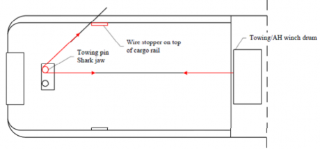
Figure 5.3 Tow Line Arrangement
504. Shark Jaws
Shark jaws and supporting structures are to be capable of sustaining the breaking strength of the anchor line or towline considering the most extreme line arrangement (see Figure 5.3) without ex- ceeding the stress limits given in 502. 5.
505. Stern Roller
The length of stern roller (or rollers) is to be kept to a minimum, and sufficient to accommodate the widest anticipated anchor to be served.
The minimum external diameter of the stern roller is to be:
ǼZ Z G ËĒ ẀŽ mm
where ẀŽ is the nominal anchor handling wire rope diameter in mm.
The roller, pin connections, foundations and supporting structure are to be designed to the breaking
strength of the anchor line. The load is to be applied as shown in
not to exceed the following the limits given in 502. 5.
Figure 5.4. The stresses are
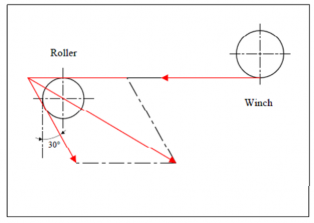
Figure 5.4 Application for Roller Load
506. A-frame or Shear Leg Type Crane
Where an A-frame or shear leg type crane is installed for anchor handling, it is to be compliance with Ch 2, Pt 9 of Rules for the Classification of Steel Ships.
certified for
26 Guidance for Offshore Support Vessels 2015
![]()
507. Tests
1. Quick Release Device Test
The effectiveness of the quick release device is to be demonstrated during trials conducted at man- ufacturers’ premises in presence of the Surveyor.
2. Drum Overload Clutch Test
The effectiveness of the drum overload clutches is to be demonstrated during winch acceptance tri- als conducted at manufacturer’s premises in presence of the Surveyor.
3. Static Bollard Pull Test
The static bollard pull test procedure is to be submitted for review by the attending Surveyor in advance of the test.
The requirements for conducting a bollard pull test on vessels of duplicate design will be specially considered on a case-by-case basis.
The static bollard pull is to be measured with the vessel at or near the maximum towing depth.
The static bollard pull is the pull that is recorded over the dency to decline.
The depth of water under the keel in the testing area should at amidships.
the maximum continuous rpm and at state of equilibrium without any ten- be at least two times the vessel draft